1. Experiment design
Every analysis initiation in cypro begins with the function designExperiment(). It opens an interactive application as shown in Figure 1.1 in which the experiment underlying the data to be analyzed can be designed. This includes the experiment type (timelapse or one time imaging) as well as the well plate design. The output is a cypro-object that does not contain any data yet but the necessary information to read in the data accordingly later on.
library(cypro)

# call the function (without any argument specification)
cypro_object_new <- designExperiment()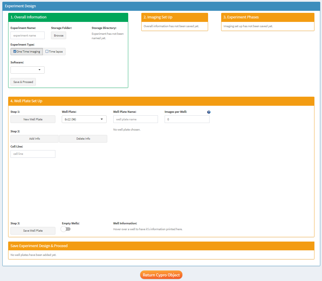
Figure 1 Interface of the function designExperiment()
Note: The color of the boxes in which each interactive application in cypro is structured change with the progress you’ve made. Clicking on ‘Save & Proceed’ of the latest box that has turned green unlocks the next box if everything you’ve done in the previous steps is valid - else an error message will tell you what still needs to be done.
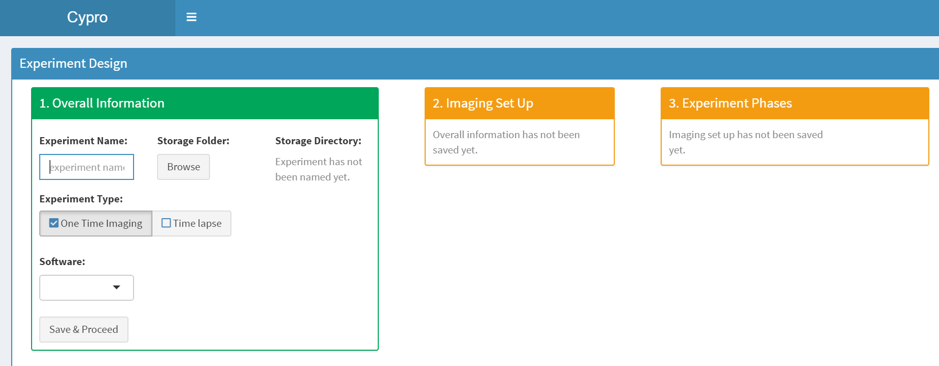
Figure 2 The coloring pattern of the boxes repeats itself in every cypro application.
1.1 Overall Information
This part includes basic information as the name of the experiment and a folder in which to store the object by default.

Figure 3 Provide overall information.
1.2 Imaging Set Up & 1.3 Experiment Phases
Providing information about the imaging set up is only necessary in case of time lapse experiment data. (The set up of one time imaging will always be the same - one image). In case of timelapse experiments you can specify the set up and, in particular, if any kind of time displaced changes in the conditions have taken place during the imaging process. In cypro we refer to that as phases. In this example the experiment was split in two phases whereby the second phase started from the seventeenth image.
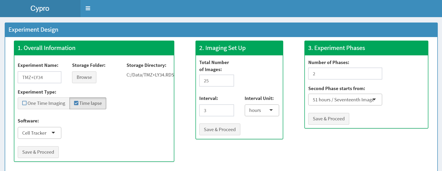
Figure 5 Imaging set up and experiment phases must be specified.
1.4 Well Plate Set Up
The fourth part of designExperiment() lets you design the well plates used for the experiment including cell line and condition.
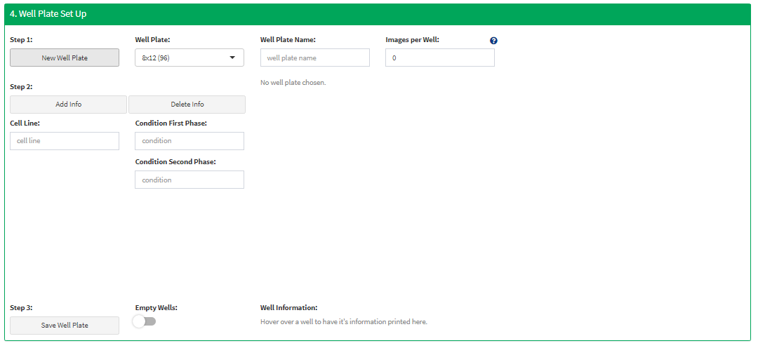
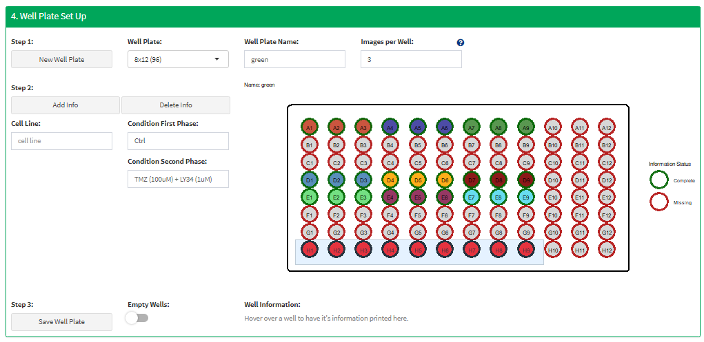
Figure 6 Design well plates interactively.
You can design as many well plates as your experiment design contained and add them repeatedly with the ‘Add Well Plate’ button. Once you are done click on save ‘Save & Proceed’ in the box below. This saves every well plate in the table you see in Figure 7 and then on the ‘Return Cypro Object’ that should have turned green by now. The return value is the cypro object that contains information about the experiment design.
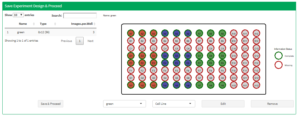
Figure 7 Saved well plates are listed below and can be added or removed afterwards
Proceed with loading the data. To get to the tutorial about how to do that click here.